TOOL ROOM II - TYPES OF CAMS PRODUCED BY CAM MILLING MACHINE
TYPES OF CAMS
What Is Cam?
When two links are joined either along a line or at a point, it is called a high pair. Two such high pairing mechanisms will be incorporated into the cam-follower system. A high pairing mechanism is known as a cam and follower.
1. Disc or Plate Cam

The disc or plate cam is a type of cam in which the follower moves radially from the center of rotations of the cam. This cam is very popular due to its simple design & compactness, which can be fitted in remote locations. Disc or plate cams have applications in IC engines and machine tools.
2. Cylindrical Cam
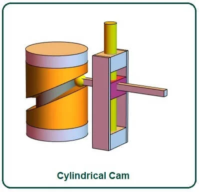
The cylindrical cam is a cam in which the cylinder is rotated about its axis, and circumferential contours are cut on the surfaces of the cylinder. They are also of two types. In the first type, a groove is cut on the surface of the cam and roller and has a positive oscillating motion.
The other has a cylinder as the working surface. In this type of cam, the spring-loaded follower translates into a cylinder rotating along the parallel axis.
3. Translating Cam
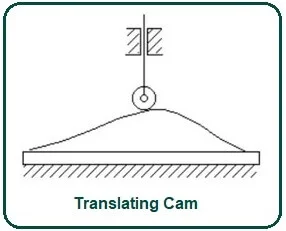
A translating cam is a type of cam in which the cam can rotate in a horizontal plane. The follower is also attached, in which the motion is interrupted with the help of a spring. Sometimes groove cams are used in which follower motion is achieved without the use of a spring.
4. Radial Cam
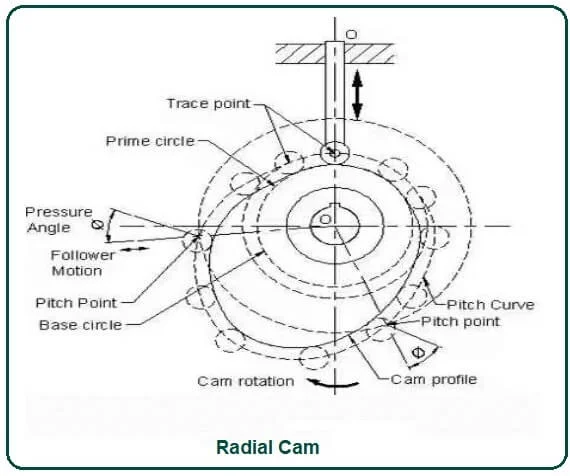
If the input link is called cam also rotates as angular momentum, then cam has rotational or angular momentum, and then we call it as radial cam.
A body with this profile is called a cam. It consists of a fixed link with an inverted pair which is the foundation or fixed link. Cam is the link of revolution. There is a revolute pair between the fixed link and the cam, and the output link is the follower.
If this cam rotates based on the profile or shape of the cam, the follower will have translational motion along with this prismatic pair between the fixed link and the follower. So in the uniform rotational motion of this cam, there will be an oscillation of the follower along with the guide.
5. Wedge Cams
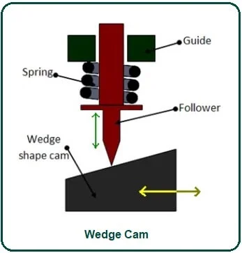
If the cam has linear motion, we call it a wedge cam. Wedge cams have a four-link mechanism, the first being a fixed link, the second link being what looks like a cam wedge. It depends on the contours of this wedge; as this cam oscillates in the horizontal direction, the follower will oscillate in the vertical direction along with this prismatic pair or this guide.
What Is a Follower?
The follower is a translating or oscillating mechanical member that follows the movement of the cam. It may touch the surface profile of the cam or may be spring-loaded. It may have a uniform velocity or a uniform acceleration speed. With the help of trailing motion, complex output motion can be obtained.
Types of Follower:
1. Linear Follower
If the follower has linear motion, we call it a translational follower. Now for a translating follower, i.e., the axis of that prismatic pair passes through the cam center; we call it radial translating. We call this a radially translating follower when the follower axis passes through the center of the camshaft.
If it has a slight offset, it means that the axis of translation of the follower does not pass through the cam center, then we call it to offset translation follower.
2. Oscillating Follower
The cam rotates as before, but it is the follower due to the shape of the cam, the follower undergoes an oscillating motion, and the follower is hinged at this point. So, it is called an oscillatory follower.
3. Knife-Edged Follower
If the follower has only a knife-edge with the cam, then we call it a knife-edge follower. The knife-edge is only theoretical as a knife-edge follower is never used due to the very high wear rate. contact stress will be too high
4. Roller Follower
The follower is hinged to a roller and is in contact with the roller cam; this is called a roller follower. It is the cam that spins, and the follower that is on here oscillates. It is used when a large power has to be transmitted like in stationary IC engines.
If there is not enough room to use a larger roller because this pin must be sufficiently large to transmit force between the cam and the follower, and the roller must be at least twice as large as the pin, then the roller requires a lot of space.
5. Flat Face Follower
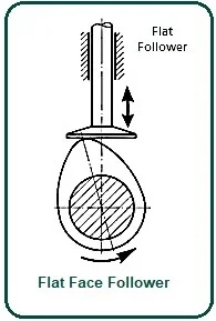
The follower surface that is in contact with the cam as a flat surface is called a flat face follower. The trailing surface may also be a curved surface rather than a plane. It is the cam that rotates and the follower that rests here that oscillates, so it is called a curved face.
If space is limited, then we can use a flat face follower if the force involved is not very large as we did in the case of automobiles.
Cam and Follower Nomenclature:
1. Trace Point
A tracepoint is a point on the follower, which describes the follower movement. For a roller follower, this is the center of the roller. So the tracepoint is the roller center, which means that the follower’s motion will be described in terms of the motions of this roller center.
If it is a flat face follower, the tracepoint we use is the point on the face of the follower that is in contact with the cam surface when the follower is at one of the extreme positions; we usually use that extreme—position when follower to nearest cam center.
2. Base Circle
The base circles are the smallest circles that can be drawn with the cam center as a center and touching cam profile, this circle we call the base circle. Therefore, the radius of the base circle, which we call Rb, is called the radius of the base circle.
3. Pitch Curve
To define the pitch curve, think of the kinetic inverse. In the kinetic inverse, it is a four-link mechanism, fixed link, cam, roller, and follower. In this four-link mechanism, this link is fixed, but in a kinematic chain, if we fix a kinematic inversion holding cam.
The location of the center of the roller will produce a curve that is parallel to the cam profile. After kinetic inversion with the cam fixed, it is the location of the tracepoint or roller center.
4. Prime Circle
The smallest circle can be drawn with the cam center as the center and tangent to the pitch curve. This circle has a center on the cam-shaft axis and is tangent to the pitch curve. This circle is called the prime circle. If the base circle radius is Rb and Rr is the roller radius, then the prime circle radius is Rp = Rb + Rr.
Cam and Follower Working Principle:
It serves a general force X direction and serves as a common force Y direction and two normal force balancing Cocking moment, the moment due to the force Fn. The frictional force that would try to oppose this vertical motion would be μ times the normal force. N as normal force, then it will μN. During the upward movement, the follower does not only have to overcome these two friction forces but to get rid of the spring force.
Large Fn is necessary to overcome the frictional force, and the vertical component of Fn will overcome these two frictional forces and the spring force, while during the downward motion, the spring force is helping the followers to come down; hence the contact force Will be less.
The vertical components will be Fn cos φ; if the φ is very large, then these verticals components will be reduced. As a result, during the upward movements, the pressure angle should be low, & during the return movement, φ can be large, so φmax is more critical during the upward movement.
When designing a cam-follower system, translating follower is not jammed into its prismatic guide. The oscillating follower has very little chance of a restriction on its motion.
Application of Cam and Follower:
There are lots of applications for cams and followers as mentioned below:
- These are used in wall clocks.
- They are used in the feed mechanism of automatic lathe machines.
- Screw pieces of machinery.
- Gear cutting machinery.
- In printing machinery, this mechanism helps to screen print. The push helps to take the positions where the printing will take place, and the pull helps to print on it.
- In the hydraulic system, these are the main mechanisms.
- Even in textile-type machinery, the cam and follower mechanism help the fabric to be sewn with one push and pull.
- In that case, the mechanism is dependent on fluid pressure.
- Automated types of machinery, cams, and followers use various parts that are automatic in motion.
Comments
Post a Comment
Have a question? Feel Free to ask DTAL for any assistance.