MILLING PROCESSES
CUTTING A SPUR GEAR ON A
MILLING MACHINE
The videos below demonstrate the procedure of cutting a spur gear on a milling machine.
#1. Face and end milling operation
#4. Vertical milling operation
video 4: Vertical milling machines
MILLING OPERATIONS
Milling is a machining process that uses rotary cutters to remove material from a workpiece by advancing it into the cutter. The milling cutter is held in a spindle, which is rotated by a motor. The workpiece is usually supported on some type of fixture, which allows it to be rotated and moved in various directions. Milling machines are often classified by their power ratings, the maximum size of the workpiece that can be milled, and the size of the mill.
Milling machines are used to produce flat or curved surfaces on a workpiece by rotating the cutter about a horizontal axis. A milling machine has a table that is mounted horizontally and a spindle that is mounted vertically. The spindle can be rotated in any direction by means of gears and clutches. The milling cutter is held in the spindle and can be moved up and down, and in and out, to cut the desired surface.
Milling operations
1. Plain or slab milling

Plain milling is the operation of producing flat horizontal surface parallel to the axis of the cutter using a plain milling cutter.
2. Face milling

The method of producing flat surface on the which is at the right angle to the axis of rotation of the cutter is called as face milling.
3. Angular or bevel milling.

It is the operation of machining a flat surface at an angle other than the axis of the revolving cutter. The cutter used may be a single or double angle cutter depending upon whether a single surface is to be machined or two mutually inclined surfaces simultaneously.
4. Straddle milling

Straddle milling is the operation of producing two vertical flat surfaces on both sides of the job by using two side milling cutters which are separated by collars. Straddle milling is very commonly used for milling square and hexagonal surfaces.
5. Gang milling

Gang milling is the production of many surfaces of a job simultaneously by feeding the table against a number of required cutters. The two plain milling cutters have helical teeth of opposite hands. This method of operation saves machining time and hence it is widely used in mass production.
6. Form milling
Form milling is the operation of producing irregular surfaces or contours by using required form cutters. The irregular shape may be convex, concave or any other shape.
7. End milling
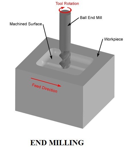
It is the operation of producing both peripheral and face milling operation simultaneously generates vertical, horizontal or angular surfaces by using a end milling cutter. It is used for milling slots, grooves, keyway etc.
8. T slot milling
Milling of t-slots is produced in two or three stages. In the first operation, the end milling operation or a plain slot is made by using an end milling cutter.

In the second operation. T-slot is made by using the t-slot cutter to enlarge the slot and to mill the bottom face of the slot.
9. Gear cutting
the gear cutting operation involves cutting of different types of gears on a milling machine.

It is performed by using a form relieved cutter which is having the profile corresponding to the required tooth shape of the gear. Equally spaced gear teeth are cut on a gear blank by holding the work on a universal dividing head and then indexing it.
SECTION 3
You may also be interested in the following article about milling formulae
Formulas for Milling Operation
Milling is the machining process that uses a rotary cutter to remove material by moving a cutter across the workpiece. This can be done on one axis or several axes, the speed and pressure of the cutter head are in a different directions.
We are going to look at some milling formulas for ease on the milling machine. Following are the important milling formulas that are very useful while performing any milling operation in a milling machine. Let’s see this one by one.
Milling Formulas
Following are the important terms used to determine the milling formula:
- Cutting speed
- Effective cutting speed
- Spindle speed
- Feed
- Maximum chip thickness
- Metal removal rate
- Specific cutting force
- Depth of cut
- Number of cutter teeth
- Machining time
Read Also: List of Important Terms Used in Lathe Machine Formula.
#1 Cutting Speed
The cutting speed of a milling cutter is its circumferential linear motion that results from rotation. It is expressed in meters per minute. The cutting speed can be obtained from the formula:
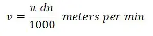
where,
- v = it is the speed of the cutter in m per min.
- d = cutter diameter in mm.
- n = Speed of the cutter in r.p.m.
#2 Effective Cutting Speed
It indicates the surface speed over the effective diameter (DCap). This is necessary in order to determine the correct cutting data at the actual depth of cut (ap).
It is used when you are working with round cutters, ball nose end mills, and cutters with large corner radii, as well as the cutter’s entry angle is less than 90 degrees.
#3 Spindle Speed
It is the number of revolutions per minute made by the milling tool on the spindle. This value is determined by the recommended cutting speed value for an operation.
#4 Feed
The feed in a milling machine is defined as the rate with which the workpiece advances under the cutter. The feed is expressed to the milling machine in the following three different ways:
1. Feed per tooth (Sz)
It is the distance that the work advances in the time between joining by two successive teeth is known as feed per tooth. It is usually represented in millimeters per tooth of the cutter.
2. Feed per revolution (Srev)
It is the distance that the work advances in the time the cutter turns through one complete revolution is known as feed per revolution. It is represented in millimeters per revolution of the cutter.
3. Feed per minute (Sm)
It is the distance by which the work moves in one minute is known as feed per minute. It is usually represented in millimeters per minute.
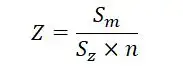
The feed per tooth, the feed per cutter revolution, and the feed per minute are related by the formula which is given below.

where,
- Z = number of teeth in the cutter.
- n = Speed of the cutter in r.p.m.
#5 Maximum Chip Thickness
This is the result of cutter engagement as it refers to (fz). Chip thickness is a required value when deciding whether to use the most productive table feed per tooth feed.
Average chip thickness: It is also a useful value in determining the specific cutting force used for net power calculations.
Checkout: What is Gear Cutting? Their Types [Advantages & Disadvantages]
#6 Metal Removal Rate
This is the volume of metal removed in cubic mm per minute (inch3/minute). It is designed using values for cutting depth, width, and feed.
#7 Specific Cutting Force
A material constant is a factor used for strength calculations and is expressed in N/mm2.
#8 Depth of Cut
It is defined as the thickness of the material removed in one pass of the work under the cutter. The depth of cut is the perpendicular length that is measured between the original and final surface of the workpiece and is represented in mm.
#9 Number of Cutter Teeth
The number of teeth on a milling cutter should be properly designed for effective machining operation. Knowing the speed and feed to which the cutter will be subjected while in an operation, the number of cutter teeth can be derived from the feed formula. The number of cutter teeth is calculated from the equation:
The coarse teeth cutter having a lesser number of teeth on their periphery are efficient in metal machining. The following are the advantages of a coarse teeth cutter.
- Greater chip space may be provided.
- Cutter tooth cross-section may be increased thereby increasing its strength.
- A greater amount of rake angle can be provided on the cutter.
- Less power is required to drive the cutter.
- Less sliding friction is produced between the tooth and the work. This reduces the development of heat.
- Longer life of the cutter may be obtained as the number of regrinds can be increased.
#10 Machining Time
The machining length (lm) is divided by the table feed (vf). The time required for any operation to mill the surface can be calculated from the formula:

where,
- T = it is the time required to complete the cut in minutes.
- L = it is the length of the table travel to complete the cut in mm.
- Ss = it is the feed per tooth in mm.
- Z = it is the number of teeth in the cutter.
- n = it is the cutter r.p.m.
The figure shows the length of the table travel ‘L’ is composed of two parts: the length of the work “C” and the approach length “A”. The approach “A” is the distance through which the cutter must be moved before the full depth of cut is reached.
#1 Approach length for plain milling cutter:

Approach “A” for a plain milling cutter can be determined by the equation:

where,
- A = the approach in mm.
- B = the depth of cut in mm.
- C = the diameter of the cutter in mm.
#2 Approach length for face milling cutter:

Referring to the above figure, the approach length for a face milling cutter can be calculated from the equation:

where,
- A = it is the length of approach in mm.
- D = it is the cutter diameter.
- B = it is the width of the work.
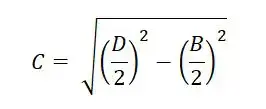
Substituting the value of “C” in equation “A”


Read Also: Formation of Chips In Metal Cutting

Let’s Consider One Example
#1 Example
Evaluate the cutting parameters for the slab milling operation for the following date:
- Milling cutter diameter = 100 mm
- Cutter speed = 500 r.p.m
- Width of cutter = 100 mm
- Depth of cut = 5mm
- Table feed = 100 mm/min
- Length of workpiece = 50 cm
- Width of workpiece = 80 mm
- Number of teeth in cutter = 8
Ans: Cutter diameter = 100 mm, cutter speed = 500 r.pm.

MRR = b.d.F
b = width of job = 80 mm, d = depth of cut = 5 mm, F = Table feed = 100 mm/min.

l = 500 mm, Here y = 4 mm


Conclusion
This is a complete list of milling formulas and definitions that are useful in any milling process and milling cutter. Understanding how to calculate accurate cutting speed, feed per tooth, or metal removal rate and machining time is very important for good results in any milling operation.


Comments
Post a Comment
Have a question? Feel Free to ask DTAL for any assistance.