The main purpose of this site is to equip the learners from Engineering Departments and other departments with technical and practical knowledge in the field through educational study materials, videos and models. This targets the learners in Technical institutions.
Let's embrace the technology in learning environment.
LATHE MACHINES
Get link
Facebook
X
Pinterest
Email
Other Apps
-
TYPES OF LATHE MACHINES & THEIR USES
The lathe is defined as the machine tool, which is used for different machining operations such as turning, facing, threading, etc.
A lathe machine is a machine that holds the workpiece on a chuck and tool on a toolpost, the lathe machine rotates the workpiece about an axis to perform different operations such as turning, facing, chamfering, thread cutting, knurling, drilling, and more with tools that are applied to the workpiece to design an object with symmetry about that axis.
The main function of a lathe is to remove the metal from a workpiece to give a required size and shape. In a lathe machine, the tool is held, and a workpiece is rotating about an axis rotation to perform various operations with different tools.
The lathe machine is primarily used to produce cylindrical surfaces and plane surfaces at a right angle to the axis of rotation. It can also produce tapers and bellows etc. Most suitable lathes can also be still used to produce most solids of revolutions, plane surfaces & screw threads, etc.
The following are the main parts of lathe machine:
Bed
headstock
Carriage
Feed mechanism
Tailstock
Screw or thread cutting mechanism
Feed rod
Lead screw
#1 Bed
The lathe bed is the base of the machine, which is a solid structure. It should be provided strictly under heavy pressure. On top of the bed, has the V-type of guideways include the angle of 90°.
There are two guideways provided, inner ways and outer ways, which are accurately machined to make them parallel to the axis. The lathe should take up the various vibrations, which are causing due to different types of force. The guideways provide sliding surfaces to the carriage and the tailstock.
The lathe bed must resist stresses due to the results of two important forces,
The downward cutting force on the tool
The force tends to move the tool away from the workpiece in a horizontal direction.
H5: Tumbler gears – forward/reverse and engage/disengage,
H6: Quick change gearbox with 4 selectors (3 levers),
H7: Lead screw,
H8: Feed screw,
H9: Forward reverse switch,
H10: Change gear cover
It is located on the left-hand side of the lathe bed. It has a hollow spindle and different types of mechanisms for driving and changing the speed of the spindle.
In this case, the speed increases when the belt shifts from larger to smaller diameter pulleys. The spindle is made up of nickel, chrome steel, and carbon steel. The front end of the spindle hole is taper for holding the centers perfectly.
The speed changing is based on the following conditions,
The type of material to be cut
Hard and tough materials like cast iron – slow speed
Soft materials like aluminum, brass – high speed.
Type of cutting tool material
For high – speed hard tools made of tungsten carbide is used.
For slow – speed medium hardness tool is used.
The type of finish-finishing cut-small depth-high speed
Rough cut – high depth – low speed.
The diameter of the workpiece
For large diameter workpiece – low speed
For smaller diameter workpiece – high speed
Type of operation
For turning, boring, drilling – high speed
For thread cutting, tapping, reaming – low speed
#3 Tailstock
The tailstock is located on the right-hand side of the lathe bed. The tailstock supports the other end of the workpiece when it is machining between two centers.
It holds the tool rigidly and perfectly for performing operations such as drilling, reaming, tapping, and boring. It can move along the guideways and can clamp in any position on the bed.
The tailstock is consist of the dead centre, spindle, adjusting screw, hand wheel, etc. The spindle can move forward and backward of the body called barrel by means of a handwheel. The keyway is provided on the inside surface of the barrel to hold the dead centre.
The carriage is one of the most important parts of the lathe tool and it will serve as a supporting, moving, and controlling part of the cutting tool.
4.1 Saddle
It is ‘H’ shaped. The saddle fits over the bed and slides along the guideways by carrying the cross slide and tool post. It can lock in any position in its movement.
4.2 Cross Slide
It is an attachment to the saddle and to the compound rest. The cross slide move by the turning handwheel. Transverse movement is obtained when the nut mounted on the feed screw is engaged with the binder screw of the cross slide.
When a taper turning attachment is used the binder screw is open to disconnect the cross slide from the crossfeed screw and the cross slide is attached to the guide block. Cross slide can move automatically when the pinion is keyed to the crossfeed screw is in mesh with the apron gearing.
4.3 Compound rest
It is a circular base, graduated in degrees and it is used to obtain angular cuts and tapers of the variable cross-section. It consists of a compound slide handwheel, compound slide feed screw, compound slide nut. The compound slide handwheel is mainly used in taper turning operations to give the feed.
4.4 Toolpost
The tool post is placed above the compound rest, and it holds the tool firmly. There are different types of tool post,
Single screw tool post
Four-way tool post
Eight-way tool post
#5 Feed Mechanism
The amount of tools relative to the workpiece is called ‘Feed.’
A lathe tool has 3 types of feed
Longitudinal feed: Here the tool moves parallel to the lathe axis. It is affected by means of the carriage movement.
Crossfeed: Here the tool moves at right angles to the lathe axis.
Angular feed: By adjusting the compound slide and swivelling it to the required angle to the lathe axis.
Cross and longitudinal feeds are both hand and power operated, but angular is only hand operated.
#6 Screw or Thread Cutting Mechanism
The lathe is important to the machine tool, which is used to cut the required type of threads on a given work. The rotation of the screw is used to move the tool along the workpiece to produce the screw threads. The half-nut mechanism is used in the lathe.
#7 Feed Rod
It is a long shaft having a keyway extending from the feed box across and in front of the bed. The power is transmitted from the lathe spindle to the apron gears through the feed rod.
The feed rod is mainly used to move the carriage or cross slide for the operations such as turning, boring, facing, and all other considering the thread cutting operation.
#8 Leadscrew
It is a long threaded shaft used for only thread cutting operations. The lead screw is in an arranged position in all operations from the gearbox. It may also be used to give the motion for turning, boring, etc., in the lathes, which are equipped with a feed rod.
Following are the seven different types of lathe machine:
Speed Lathe Machine
Engine Lathe Machine
Bench Lathe Machine
Toolroom Lathe Machine
Capstan and Turret Lathe Machine
Special-purpose lathe machines
Automatic Lathe Machine
CNC lathe machine
#1 Speed Lathe Machine
These types of lathe machines are simple in construction. It has a bed, headstock, tailstock, and tool post mounted on the adjustable slide. There is no feed box lead screw or carriage.
The tool is mounted on the adjustable slide and is fed into the work purely by hand control. This characteristic of the lathe machines has a speed range from 1200 to 3600 rpm. The headstock construction is very simple and has only 2 or 3 spindle speeds available.
Speed lathe machine has less depth of cut. Light force and high speed made this to use this part woodworking, spinning, centering, and polishing. The name speed lathe has been given because of the very high speed of the headstock spindle.
#2 Engine Lathe Machine
Engine lathe is the most widely used lathe machine. These machines are driven by the gear mechanism or pulley mechanism. The name engine lathe is given because of the earlier lathe were driven by steam engines.
Engine lathe machine has all the parts similar to that of speed lathe. Such as bed, headstock, tailstock, etc. The headstock of an engine lathe is rigid in construction and has got an additional mechanism to get multiple spindle speeds.
Unlike the speed lathe, the engine lathe can feed the cutting tool both in the cross and longitudinal direction with reference to the lathe axis with the help of a carriage feed and leadscrew. These types of lathe machines are still used in workshops and many industries. It has three types Belt-driven, Motor-driven, and Gearhead type.
2.1 Belt Drive Lathe Machine
A lathe that receives its power from an overhead line shaft is a belt-driven lathe and is equipped with a speed cone and one or more back gears to get a wide range of spindle speeds.
2.2 Motor-Driven Lathe Machine
A lathe that receives its power from an individual motor integral with the machine is called a motor-driven lathe.
2.3 Geared-head Lathe Machine
A geared-head lathe gets its power from a constant speed motor, and all-speed changes are obtained by shifting various gears located in the headstock. It has no cone pulley.
These types of lathe machines are small in size and are used for very small precision work. Bench lathe machines are mounted on the bench. It has all the similar parts of the engine lathe and speed lathe. Bench lathe machine performs almost all the operations of the engine lathe and speed lathe. Its only difference is in size.
Toolroom lathe machine is the same as that of engine lathe but provides a wide range of speed. The spindle speed range is from very low to quite high speed up to 2500rpm.
Image is from indiamart.com
This is equipped beside the other thing, with a chuck, taper turning attachment, draw in collect attachment, steady and follower rest, pump for coolant, etc. Toolroom Lathe is costlier as compared to the engine lathe. It is mainly using in grindings, working on the tool, dies gauges, and in machining work where is accuracy is needed.
5. Capstan Lathe and Turret Lathe
Image: media.licdn.com
These types of lathe machines are used in production work. These lathe machines are the development of the engine lathe. These machines are provided with hexagonal turret heads instead of tailstock. It also consists of three tool posts.
In these types of lathe machines, multiple tools may be fitted and fed into the work in the proper sequence. The main advantage is that different operations and parts can produce in a very less amount of time. And also without changing the tool the quantity and quality are high.
Capstan and turret lathe requires more floor space than other lathe machines. Capstan and turret lathe is used for only large jobs.
As the name implies these types of lathe machines are used for special purposes and for production work. In this lathe, special operations are performed such as drilling, grinding, reaming, boring, etc.
The special-purpose lathe machines are:
Wheel lathe machine
Gap bed lathe machine
T-lathe machine
Duplicating lathe machine
Missile lathe machine
1. Wheel Lathe Machine
The wheel lathe is made for finishing the journals and turning the thread on the railroad, automobile cars, and locomotive wheels.
2. Gap Bed Lathe
The gap bed lathe, in which a section of the bed adjacent to the headstock is removable, is used to swing extra large diameter pieces.
3. T-Lathe
The “T -lathe” is used for machining rotors for jet engines. The axis of the lathe bed is at right angles to the axis of the headstock spindle in the form of a T.
4. Duplicating Lathe
The duplicating lathe machine is one of the duplicating the shape of a flat or round template onto the workpiece. Mechanical, pneumatic, and hydraulic devices are all used to coordinate the movement of the tool to reproduce accurately the shape of the template.
5. Missile Lathe Machine
The missile lathe machine which has a very large swing for accommodating long missile components of very large diameter is the most modern and latest in lathe design.
7. Automatic Lathe
In these types of lathe machines, all the work is done automatically. These are the high-speed heavy-duty, production lathes. In these types of lathe machines, once the tool is set, it performs all the operations automatically to finish the job.
Here the change of tools and feed is automatic. The single operator can control 5 to 6 automatic lathes at a time.
Lathe machine performs different operations such as turning, facing, taper turning, knurling, grooving, parting off, electric turning, thread cutting, reaming, etc. Let it take one by one as follows.
8. CNC Lathe Machine
These types of lathe machines are operated with a precise set of design instructions. A CNC (computer numerical control) lathe is a machine tool that rotates the workpiece around the main spindle, while a cutting tool cuts the workpiece into a desired shape and size.
A simple CNC lathe operates on two axes with the cutting tool in a fixed position on an 8 to 24 station turret. CNC lathe ensures consistent product quality and does not require highly skilled operators to operate the machine. On the other hand, CNC machines are more expensive than manually operated machines.
The lathe machine attachments are additional types of equipment used for some special and specific purposes. The important lathe attachments are
Stops
Rests
Taper turning attachments
Milling attachments
Grinding attachments
Gear attachments
Boring attachments
TYPES OF LATHE MACHINE OPERATIONS
Lathe Machine Operations
A lathe is a machine that rotates the workpiece about an axis to perform different operations such as turning, facing, taper turning, knurling, grooving, parting off, thread cutting, reaming, etc.
To perform different lathe machine operations on a lathe, the workpiece may be supported and driven by any one of the following methods:
Workpiece held between centres and tool driven by carriers and catch plates.
Workpiece held on a mandrel which is supported between centres and driven by carriers and catch plates.
Held and driven by chuck with the other end supported on the tailstock centre.
Held and driven by a chuck or a faceplate or an angle plate.
The above methods of holding the work may be classified under two heading:
Workpiece held between centres.
Workpiece held by a chuck or any other fixture
Types of Lathe Machine Operations
The lathe machine operations are classified into three main categories and are as follows.
Following are the Lathe machine operations done either by holding the workpiece between centres or by a chuck:
Turning Operation
Plain or Straight Turning
Rough Turning
Shoulder Turning
Taper Turning
Eccentric Turning
Facing Operation
Chamfering Operation
Knurling Operation
Thread cutting Operation
Filing Operation
Polishing Operation
Grooving Operation
Spinning Operation
Spring Winding
Forming
Lathe machine operations which are performed by holding the work by a chuck or a faceplate or an angle plate are:
Drilling
Reaming
Boring
Counterboring
Taper boring
Tapping
Undercutting
Internal thread cutting
Parting-off
The operation which is performed by using special attachments are:
1. Operations Done by Holding Workpiece Between Centres
Turning:
It is the most common type of operation in all lathe machine operations. Turning is the operation of removing the excess material from the workpiece to produce a cylindrical surface to the desired length.
The job held between the centre or a chuck and rotating at a required speed. The tool moves in a longitudinal direction to give the feed towards the headstock with proper depth of cut. The surface finish is very good.
1. Straight Turning:
The workpiece is held on the chuck and it is made to rotate about the axis, and the tool is fed parallel to the lathe axis. The straight turning produces a cylindrical surface by removing excess metal from the workpiece.
2. Rough Turning:
It is the process of removal of excess material from the workpiece in minimum time by applying high rate feed and heavy depth of cut. in rough turning the average depth of cut 2mm to 4mm can be given and feed is from 0.3 to 1.5mm per revolution of the work.
3. Shoulder Turning:
When a workpiece has different diameters and is to be turned, the surface forming steps from one diameter to the other is called the shoulder, and machining this part of the workpiece is called shoulder turning.
Eccentric turning:
When a cylindrical surface two separate axis of rotation, with the first axis, is offset to the other axis then such a workpiece is machined by the operation called eccentric turning. Here three sets of centre holes are drilled.
By holding the workpiece at these three centres the machining operation for each of the surface can be completed.
Taper Turning:
A ”taper” is the uniform increase or decrease in the diameter of the workpiece and measured along with its length.
Taper turning means to produce a conical shape by a gradual reduction in diameter from a cylindrical workpiece.
The amount of taper in the workpiece is usually specified on the basis of the difference in diameter of the taper to its length. It is known as a cone and it is indicated by the letter K.
It has the formula K = D-d / 1 to produce the taper on the workpiece.
D = Larger diameter of taper.
d = Small diameter of taper.
In the case of a lathe, the taper on a given workpiece is obtained by tuning the job and feeding the tool at an angle to produce a gradual increase or decrease in the diameter of the workpiece.
The two important types of tapers are,
”More taper” here, the angle is very small and varies from 1.4 to 1.5°.
”Metric taper” is available in seven standard sizes with standard taper angles.
Methods of taper turning,
Form tool method
Combined feeds method
Compound rest method or swivelling compound rest method
Tailstock set over method
Taper turning attachment method
1. Form tool method
Here the taper length obtain is equal to the width of the form tool. To obtain the required size of the taper the form tool is fed slowly straight into the workpiece by operating the cross slide perpendicular to the lathe axis.
This is the simplest method of taper turning. It is limited to obtain small taper length such as chamfering the side of the workpiece. The method is done at a faster rate.
2. Combined feeds method
The combined feed is made with the movement of a tool in longitudinal and lateral direction simultaneously while moving the workpiece.
The taper, which we are going to obtain, is equal to the resultant to the magnitude of the longitudinal and lateral feeds. Changing the feeds rates in both directions can change the direction and the taper angle.
3. Compound rest swivel method
Here the workpiece rotates and the cutting tool is fed at an angle by swivelled compound rest. The base of the compound rest is graduated in degrees.
The taper angle is the angle at which the compound rest to be rotated is calculated by using the formula tanα = D-d / 21, where, D= bigger diameter, d = smaller diameter, l = length of the workpiece.
Compound rest can be swivelled to the required angle α. Once the compound rest is set to a particular angle then the tool is moved by compound rest and wheel.
4.Taper turning attachment method
This method is similar to the compound rest method.
Here the job or workpiece rotates and the tool is fed at the taper angle α.
In this, arrangement, which has guide block graduated in degrees, with the help of this the block can be required taper angle to the lathe axis.
The taper angle is calculated similarly to the compound rest method using the formula: tanα = D-d / 21.
Advantages of taper turning attachment:
Internal tapers can be obtained accurately.
large size tapers can be easily obtained.
Once the attachment is set the taper turning operation can do at a faster rate.
By setting the taper angle to ‘zero’ we can carry out plain turning.
Disadvantages of taper turning attachment:
It requires additional mounting facilities.
Fitting and removing attachment consume more time.
The attachment has to take large forces.
Tailstock set over method:
Here the workpiece on the job is tilted at the required taper angle. The tool is fed parallel to the axis.
The tilting of the workpiece or the job to the required taper angle is achieved by the movement of the tailstock with the help of tailstock set over the screw. This method is useful for small tapers.
Facing:
It is an operation of reducing the length of the workpiece by feeding the perpendicular to the lathe axis. This operation of reducing a flat surface on the end of the workpiece. For this operation, regular turning tool or facing tool may use. The cutting edge of the tool should set to the same height as the centre of the workpiece.
Facing consist of 2 operations
Roughing: Here the depth of cut is 1.3mm
Finishing: Here the depth of cut is 0.2-0.1mm.
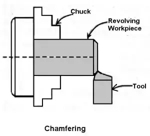
Chamfering operation:
It is the operation of getting a bevelled surface at the edge of a cylindrical workpiece. This operation is done in case of bolt ends and shaft ends. Chamfering helps to avoid damage to the sharp edges and protect the operation getting hurt during other operations. Chamfering on bolt helps to screw the nut easily.
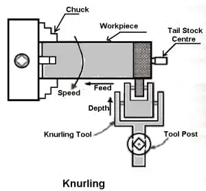
Knurling operation:
It is an operation of obtaining a diamond shape on the workpiece for the gripping purpose. This is done to provide a better gripping surface when operated by hands. It is done using a knurling tool. The tool consists of a set of hardened steel roller, and it is held rigidly on the toolpost.
Knurling is done at the lowest speed available on a lathe. It is done on the handles and also in case of ends of gauges. The feed varies from 1 to 2 mm per revolution. Two or three cuts may be necessary to give the full impression.
Thread cutting:
It is the important operation in the lathe to obtain the continuous ”helical grooves” or ” threads’‘.
When the threads or helical grooves are formed on the out surface of the workpiece is called external thread cutting. When the threads or helical grooves are formed on the inner surface of the workpiece is called internal thread cutting. The workpiece is rotating between the two centres i.e., live centre and dead centre os the lathe.
Here the tool is moved longitudinally to obtain the required type of the thread. When the tool is moved from right to the left we get the left-hand thread. Similarly, when the tool is moved from left to the right we get the right-hand thread.
Here the motion of the carriage is provided by the lead screw. A pair of change gears drives the lead screw and by rotating the handle the depth of cut can be controlled.
Filling:
It is the finishing operation performed after turning. This is done on a lathe to remove burrs, sharp corners, and feed marks on a workpiece and also to bring it to the size by removing the very small amount of metal.
The operation consists of passing a flat single-cut file over the workpiece which revolves at a high speed. The speed is usually twice that of turning.
Polishing:
This operation is performed after filing to improve the surface quality of the workpiece. Polishing with successively finer grades of emery cloth after filing results in a very smooth, bright surface. The lathe is run at high speeds from 1500 to 1800m per min, and oil is used on the emery cloth.
Grooving:
It is the process of reducing the diameter of a workpiece over a very narrow surface. It is done by a groove tool. A grooving tool is similar to the parting-off tool. It is often done at the end of a thread or adjacent to a shoulder to leave a small margin.
Spinning:
it is the process of forming a thin sheet of metal by revolving the job at high speed and pressing it against a headstock spindle. Support is also given from the tailstock end.
Spring Winding:
Spring winding is the process of making a coiled spring by passing a wire around a mandrel which is revolved on a chuck or between centers. A small hole is provided on the steel bar, which is supported by Tool Post and the wire is allowed to pass through it.
Forming:
It is the process of turning a convex, concave, or of any irregular shape. Form-turning may be accomplished by the following method:
Using a forming tool.
Combining cross and longitudinal feed.
Tracing or copying a template.
Forming tools are not supposed to remove much of the material and is used mainly for finishing formed surfaces. Generally, two types of forming tools are used straight and circular. The straight type is used for wider surface and the circular type for narrow surfaces.
2. Operations Done By Holding The Work By A Chuck
Lathe machine operations performed by holding the work by a chuck or a faceplate or an angle plate are:
Drilling:
Drilling is the operation of producing a cylindrical hole in a workpiece. It is done by a rotating tool, the rotating side of the cutter, known as a drilling drill. In this operation, The workpiece is revolving in a chuck or a faceplate and the drill is held in the tailstock drill holder or drill chuck.
The feeding is adopted is affected by the movement of the tailstock spindle. This method is adopted for the drilling of regular-shaped workpiece.
Reaming:
Reaming is the operation of finishing and sizing a hole which has been already drilled or bored. The tool is used is called the reamer, which has multi-plate cutting edges.
The reamer is held on the tailstock spindle, either directly or through a drill chuck, and is held stationary while the work is revolved at a very slow speed.
Boring:
Boring is the operation of enlarging the hole which is already drilled, punched or forged. It cannot produce a hole. Boring is similar to the external turning operation and can be performed in a lathe. In this operation, the workpiece is revolved in a chuck or a faceplate and the tools which are fitted to the tool post is fed into the work.
It consists of a boring bar having a single-point cutting tool that enlarges the hole. It also corrects out of the roundness of a hole. This method adopted for boring small-sized works only. The speed of this process is slow.
Counterboring:
Counterboring is the operation of enlarging the end of the hole through a certain distance. It is similar to shoulder work in external turning.
The operation is similar to boring and plain boring tools or a counterbore may be used. The tool is used called a counterbore. The speed is slightly less than drilling.
Taper Boring:
The principle of turning a tapered hole is similar to the external taper turning operation and is completed by rotating the work on a chuck or a faceplate. The feeding tool is at an angle to the axis of rotation of the workpiece.
A boring tool is mounted on the tool post and by swivelling the compound slide to the desired angle, a short taper hole is machined by hand feeding.
Tapping:
Tapping is the operation of cutting internal threads of small diameter using a multipoint cutting tool called the tap. In a lathe, the work is mounted on a chuck or on a faceplate and revolved at a very slow speed. A tap of the required size held on a special fixture is mounted on the tailstock spindle.
Undercutting:
Undercutting is similar to a grooving operation when performed inside a hole. It is the process of boring a groove or a large hole at a fixed distance from the end of a hole.
This is similar to the boring operation, except that a square nose parting is used. Undercutting is done at the end of an internal thread or a counterbore to provide clearance for the tool or any part.
3. Lathe Operations Done By Using Special Attachments
Lathe machine operations are performed by using special attachments:
Milling:
Milling is the operation of removing metal by feeding the work against a rotating cutter having multiple cutting edges.
For cutting keyways or grooves, the work is supported on the cross-slide by a special attachment and fed against a rotating milling cutter held by a chuck. The depth of cut is given by vertical adjustment of the work provided by the attachment.
The depth of cut is given by vertical adjustment of the work provided by the attachment. The feeding movement is provided by the carriage and the vertical movement of the cutter is arranged in the attachment.
Grinding:
Grinding is the operation of removing the metal in the form of minute chips by feeding the work against a rotating abrasive wheel known as the grinding wheel.
Both internal and external surface of a workpiece may be ground by using a special attachment mounted on the cross slide. For the grinding external surface, the work may be revolved between centers or on a chuck. For internal grinding, the work must be revolved on a chuck or faceplate.
The feeding is done by the carriage and the depth of cut is provided by the cross slide. Grinding is performed in a lathe for finishing a job, sharpening a cutter, or sizing a workpiece after it has been hardened.
SINGLE POINT CUTTING TOOL: DIAGRAM, NOMENCLATURE, MATERIAL What is a Single Point Cutting Tool? A single point cutting tool refers to a tool with a single cutting edge used in the machining process to remove material from a workpiece. A single-point cutting tool is so named because it only has one edge, unlike a multi-point cutting tool, which has multiple edges. On lathes and milling machines , single-point cutting tools are frequently used for turning, facing, and boring operations. Typically, the tool’s body is made of a more durable, more flexible material, such as steel . In contrast, the cutting edge is made of a hard, wear-resistant material, such as tungsten carbide or ceramic. Tool cutting edges are shaped and ground to produce the desired geometry, such as sharp points for drilling and rounded noses for turning. There are many factors that influence the cutting properties of tools, including their surface finish, accuracy ...
THERMODYNAMIC CYCLES Modified Rankine Cycle: Efficiency with P-v and T-s Diagrams TO EXPLORE MORE ON THERMODYNAMICS CYCLES, USE THE LINKS ATTACHED. This post explains the Rankine circle. follow the link to learn more … Read more Rankine Cycle: Processes with P-v and T-s Diagram Rankine Cycle The Rankine cycle is a modified form of Carnot cycle, in which the isothermal compression (3-4) is continued … Read more Carnot Vapour Cycle Processes & Efficiency With P-v and T-s Diagram In this post, you’ll learn what is Carnot Vapour Cycle its process and efficiency with p-v and t-s diagram. Introduction … Read more ...
SHEET METAL FABRICATION What is S heet M etal F abrication ? Sheet metal fabrication refers to the turning of flat metal sheets into metal products and structures. Typically, this technique involves transforming different types of sheet metals into parts and components. It is also a versatile process that can create a wide range of metal components made from Aluminum, Steel, Stainless Steel, Copper, Brass and Galvanized iron. In sheet metal fabrication, different techniques are usually combined to produce the desired part. The basic processes include cutting, bending, punching, stamping, welding, and finishing. These techniques complement each other and play a vital role in the successful completion of a project. What’s more, you are unlikely to go about your day without encountering sheet metal products. So, whether you’re at home, at work, or out and about, it’s highly likely that you find these products everywhere. These sheet metal has...


Comments
Post a Comment
Have a question? Feel Free to ask DTAL for any assistance.