PRODUCTION TECHNOLOGY

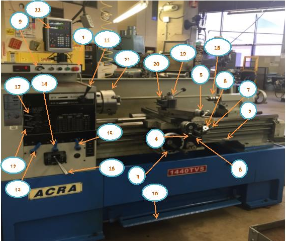
Figure 1. Parts of a lathe
1. Power On/Off
2. Spindle Forward/Reverse (flip handle up or down)
3. Carriage Handwheel 4. Cross Feed Handwheel
5. Compound Feed Handwheel
6. Carriage/Cross Feed Engage
7. Threading Half Nut
8. Threading Dial
9. Spindle Speed
10. Brake
11. Spindle High/Low Range
12. Thread/Feed Reverse (push in/pull out)
13. Feed Ranges (A, B, C)
14. Feed Ranges (R, S, T)
15. Feed Ranges (V, W, X, Y, Z) – V and Z are settings for threading
16. Gear Box
17. Gear Box Low/High
18. Tailstock
19. Tool Post
20. Toolholder
21. Three – Jaw Chuck
22. DRO (Digital Read Out) Threading/Feed Selector (see item15)


Lathe Safety
As always we should be aware of safety requirements and attempt to observe safety rules in order to eliminate serious injury to ourselves or others.
Wear glasses, short sleeves, no tie, no rings, no trying to stop the work by hand. Stop the machine before trying to check the work. Don’t know how it works? –“Don’t run it.” Don’t use rags when the machine is running.
1. Remove the chuck key from the chuck immediately after use. Do not turn the lathe on if the chuck is still in the chuck key.
2. Turn the chuck or faceplate through by hand unless there are binding or clearance issues.
3. It is important that the chuck or faceplate is securely tightened onto the lathe’s spindle.
4. Move the tool bit to a safe distance from the chuck, collet, or face plate when inserting or removing your part.
5. Place the tool post holder to the left of the compound slide. This will ensure that the compound slide will not run into the spindle or chuck attachments.
6. When installing and removing chucks, face plates, and centers, always be sure all mating surfaces are clean and free from burrs.
7. Make sure the tool bit is sharp and has correct clearance angles.
8. Clamp the tool bit as short as possible in the tool holder to prevent it from vibrating or breaking.
9. Evenly apply and maintain cutting fluids. This will prevent morphing.
10. Do not run a threaded spindle in reverse.
11. Never run the machine faster than the recommended speed for the specific material.
12. If a chuck or faceplate is jammed on the spindle nose, contact an instructor to remove it.
13. If any filing is done on work revolving in the lathe, file left handed to prevent slipping into the chuck.
14. Always stop the machine before taking measurements.
15. Stop the machine when removing long stringy chips. Remove them with a pair of pliers.
16. Make sure that the tailstock is locked in place and that the proper adjustments are made if the work is being turned between centers.
17. When turning between centers, avoid cutting completely through the piece.
18. Do not use rags while the machine is running.
19. Remove tools from the tool post and tailstock before cleaning.
20. Do not use compressed air to clean the lathe.
21. Use care when cleaning the lathe. The cutting tools are sharp, the chips are sharp, and the workpiece may be sharp.
22. Make sure the machine is turned off and clean before leaving the workspace. Always remove the chuck wrench after use, avoid horseplay, keep floor area clean. Use care when cleaning the lathe, the cutting tools are sharp, the chips are sharp, and the workpiece may be sharp.
Here are some questions which are important when running a lathe:
• Why is proper Cutting Speed important?
When set too high the tool breaks down quickly, time is lost replacing or reconditioning the tool. Too low of a CS results in low production.
Know:
• Depth of cut for Roughing.
• Depth of cut for Finishing.
Notice the largest roughing cuts range from .010 to .030 depending on the material being machined, and .002 to .012 for the finish feed for the different materials.
• Feed rate for Roughing cut
• Feed rate for Finishing cut
Notice the Feed rate for roughing cuts range from .005 to .020 depending on the material being machined, and .002 to .004 for the finish feed for the different materials.
Cutting Tool Terminology
There are many different tools that can be used for turning, facing, and parting operations on the lathe. Each tool is usually composed of carbide as a base material, but can include other compounds. This section covers the different appearances and uses of lathe cutting tools.
Figure A:depicts a standard turning tool to create a semi-square shoulder. If there is enough material behind the cutting edge, the tool can also be used for roughing. |
Figure A |
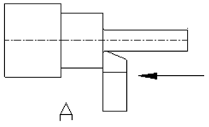
Figure B:depicts a standard turning tool with a lead angle. This angle enables for heavy roughing cuts. it is also possible to turn the tool to create a semi-square shoulder. |
Figure B |
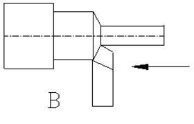
Figure C:nose has a very large radius, which helps with fine finishes on both light and heavy cuts. The tool can also be used to form a corner radius. |
Figure C |
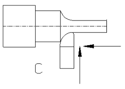
Figure D:depicts a rotated standard turning tool. Its nose leads the cutting edge to create light finishing cuts on the outside diameter and face of the shoulder. | 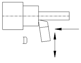 Figure D |
Figure E:depicts a form tool. Different forms can be ground into the tool, which will be reproduced onto the part. |
Figure E |
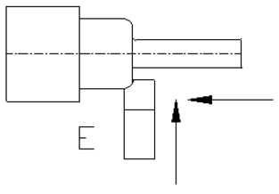
Figure F:depicts a facing tool. This cutter is used to face the end of a workpiece to provide for a smooth, flat finish. If the stock has a hole in the center, utilize a half-center to stabilize and support the workpiece. |
Figure F |
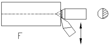
Figure G:depicts a grooving or under-cutting tool. As shown, it is used to cut grooves into the workpiece. When there are proper clearances, the tool can cut deeply, or cut to the left or right. |
Figure G |
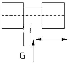
Figure H:depicts a parting tool. Parting tools cut off the stock at a certain length. This tool requires a preformed blade and holder. |
Figure H |
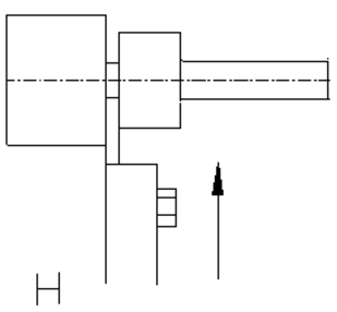
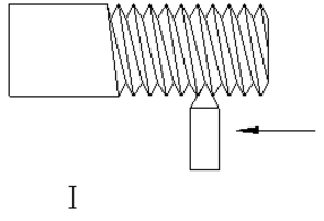
Figure I:depicts a 60° threading tool used to thread stock. |
Figure I |
To setup a Cutting Tool for Machining
• Move the toolpost to the left-hand side of the compound rest.
• Mount a toolholder in the toolpost so that the set screw in the toolholder is about 1 inch beyond the toolpost.
• Insert the proper cutting tool into the toolholder, having the tool extend .500 inch beyond the toolholder.
• Set the cutting tool point to center height. Check it with straight rule or tailstock.
• Tighten the toolpost securely to prevent it from moving during a cut
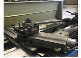
Figure 2: Toolpost and Toolholder
To Mount Workpiece in Lathe
• Check that the line center is running true. If it is not running true, remove the center, clean all surfaces, and replace the center. Check again for trueness.
• Clean the lathe center points and the center holes in the workpiece.
• Adjust the tailstock spindle until it projects about 3 inch beyond tailstock.
• Loosen the tailstock clamp nut or lever.
• Place the end of the workpiece in the chuck and slide the tailstock up until it supports the other end of the workpiece.
• Tighten the tailstock clamp nut or level.
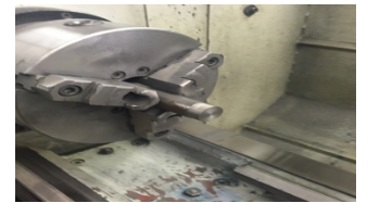
Figure 3: Workpiece in Lathe
Installing a Cutting Tool
• Tool holders are used to hold lathe cutting tools.
• To install, clean the holder and tighten the bolts.
• The lathe’s tool holder is attached to the tool post using a quick release lever.
• The tool post is attached to the machine with a T-bolt.
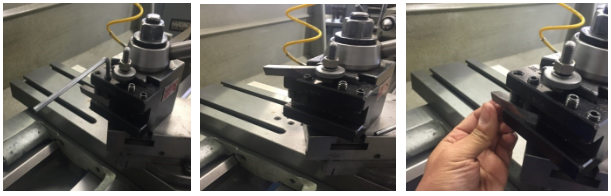
Figure 4: Installing a Cutting Tool
Positioning the Tool
To reposition the cutting tool, move the cross slide and lathe saddle by hand. Power feeds are also available. Exact procedures are dependent on the machine. The compound provides a third axis of motion, and its angle can be altered to cut tapers at any angle.
1. Loosen the bolts that keep the compound attached to the saddle.
2. Swivel the compound to the correct angle, using the dial indicator located at the compound’s base.
3. Tighten the bolts again.
4. The cutter can be hand fed along the chosen angle. The compound does not have a power feed.
5. If needed, use two hands for a smoother feed rate. This will make a fine finish.
6. Both the compound and cross slide have micrometer dials, but the saddle lacks one.
7. If more accuracy is needed when positioning the saddle, use a dial indicator that is attached to the saddle. Dial indicators press against stops.
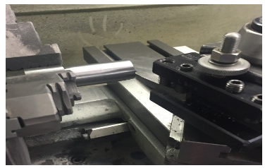
Figure 5: Positioning the Tool
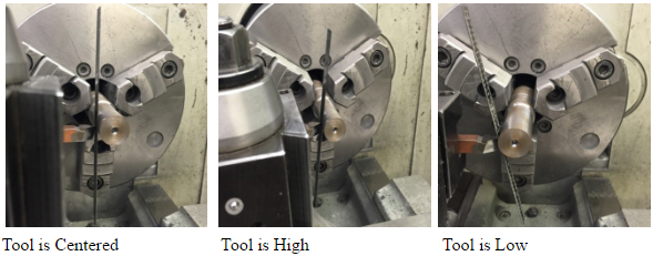
Centering the Workpiece
Steel Rule
1. Place the steel rule between the stock and the tool.
2. The tool is centered when the rule is vertical.
3. The tool is high when the rule is lean forward.
4. The tool is low when the rule is lean backward.
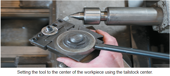
Tailstock Center
1. Reference the center of the tailstock when setting the tool.
2. Position the tip of the tool with the tailstock center.
UNIT TEST
1. Please list the ten most important parts of the Lathe.
2. Please list five Lathe safety guidelines.
3. Why is cutting speed important?
4. What is a Toolholder?
5. Where do you mount a Toolholder?
6. How far do you extend the cutting tool in the Toolholder?
7. Please list three different cutting tools.
8. Please describe the positioning of the tool.
9. Explain how to center the workpiece.
10. What are the two way to center the workpiece?
CUTTING SPEED, FEED, DEPTH OF CUT, MACHINING TIME IN LATHE MACHINE
Lathe machine formula for cutting speed, feed, and depth of cut
A lathe machine is a machine that holds the workpiece on a chuck and tool on a toolpost, the lathe machine rotates the workpiece about an axis to perform different operations such as turning, facing, chamfering, thread cutting, knurling, drilling, and more with tools that are applied to the workpiece to design an object with symmetry about that axis.
The following are the lathe machine formula commonly used to calculate in turning operations:
- Cutting speed
- Feed
- Depth of cut
- Machining time
1. Cutting Speed

The cutting speed (v) of a tool is the speed at which the metal is removed by the tool from the workpiece. In a lathe, it is the peripherical speed of the work past the cutting tool expressed in meters per minute.
Where,
- d – is the diameter of the work in mm.
- n – is the r.p.m of the work.

In the British system, cutting speed is expressed in feet per minute and diameter of the work in inches.
Where,
- d – is the diameter of the work in inches, and
- n – is the r.p.m of the work.
The cutting speed, direction of feed and depth of cut to be given to a workpiece are shown in the figure below.
Example 1)

A steel shaft of 25mm diameter is turned at a cutting speed of 50 metres per minute. Find the r.p.m. of the shaft.
In practice, when the calculated speed is not available in the machine the next lower value is selected.
2. Feed
The feeds of the cutting tool in lathe work are the distance the tool advances for each revolution of the work. A feed is expressed in millimetres per revolution.
In the British system, it is expressed in inches per revolution.
Increased feed reduces cutting time. But increased feed greatly reduces the tool life. The feed depends on factors such as size, shape, strength and method of holding the component, the tool shape and it’s setting as regards overhang, the rigidity of the machine, depth of cut, power available, etc. rougher feeds are applied for roughing and finer feeds for finishing cuts.
3. Depth of Cut

The depth of cut (t) is the perpendicular distance measured from the machined surface to the uncut surface of the workpiece. In a lathe machine, the depth of cut is shown as follows:
Where,
- d1 – diameter of the workpiece surface before machining.
- d2 – diameter of the machined surface.
Another factor remaining fixed, the depth of cut changes inversely as the cutting speed. For general purpose, the ratio of the depth of cut to the feed varies from 10:1
4. Machine Time
The machining time in the lathe work can be calculated for a particular operation if the speed of the job, feed and length of the job is known.
If “s” is the feed of the job per revolution expressed in mm per revolution and “l” the length of the job in mm, then a number of revolutions of the job required for a complete cut will be: l/s.

Therefore, the time is taken for a complete cut = l / s X n min.
If the r.p.m. of the work is n, the time is taken to revolve the job through l/s number of revolutions for a complete cut will be:
Example 2)

Find the time required for one full cut on a workpiece of 350mm long and 50mm in diameter. The cutting speed is 35 metres per minute and the feed is 0.5mm per revolution.
Average cutting speed expressed in meter per minute for different operations in a lathe using an H.S.S. tool

Average cutting speed, feed and depth of cut for different tool materials:

Cutting Tool Signature
The signature is a sequence of numbers listing the various angles, in degrees, and the size of the nose radius. This numerical method of identification has been standardized by the American Standards Association.
The seven elements that comprise the signature of a single-point cutting tool are always started in the following order:
- Back Rack Angle
- Side Rake Angle
- End Relief Angle
- End Cutting Edge Angle
- Side Cutting Edge Angle
- Nose Radius
Thus a tool with shaped specified as 8-14-6-6-6-15-4 has 8° back rake, 14° side rack, 6° end or side relief, 6° end cutting edge and 15°side cutting edge angles, and 4mm nose radius.


Comments
Post a Comment
Have a question? Feel Free to ask DTAL for any assistance.